Click to view our Accessibility Statement or contact us with accessibility-related questions


PRODUCTS YOU MAY LIKE

Trending Posts in Mechanical Keyboards

lantz
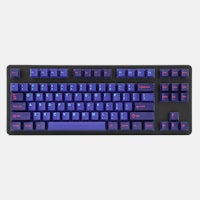
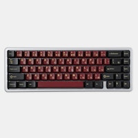
Red Samurai on a 75%
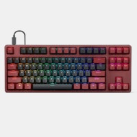
Corsair K65 Plus Wireless GMK Red Samurai Moondrop Tactile Tessence
Apr 19, 2024

Keyled
My PRECIOUS!!!!
All that sweat and money paid off. I will use it wisely. Tokyo 60 GMK Serenity Gateron Oil KIng
Apr 19, 2024

TotallyJaded
How do you do per-key RGB lighting on a Shift V2?
I saw the online configurator that lets you do this on the Shift V1, where it spits out a compiled firmware file to flash. The V2 doesn't seem to have this function in the Windows configurator, though. I can't imagine the answer here is "you're going to have to manually write the hex for every key in QMK, compile it, and flash that".
Apr 18, 2024

AiheyStudio
Favorite Artisans
Dragon Pillar Artisan Keycaps Creative Resin Keycaps for 6.25u and 7u Space Bars
Discover the allure of our Dragon Pillar Artisan Keycaps – unique resin keycaps designed to adorn your 6.25u and 7u space bars. Crafted with creativity and precision, each keycap features an...
Apr 18, 2024


lwthunder
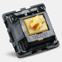
Drop CTRL V2 Mechanical Keyboard PCBA
If I want some hot-swap socket for replacement, where I can buy to ensure it fits this PCBA?
Apr 17, 2024
Drop Refurbished
Like-new products you can trustDrop Rewards
Get $5 for every 500 points you earn! Learn more
Drop Keyboard Club
Become a member and expand your keycap collectionCollaborate With Us
For Brands & DesignersFollow Drop
To install, I've tried placing the plate/pcb into the top section of the case, then laying the bottom section over it, and inserting the screws. However, when I apply the screws, they cannot grip the holes inside the case. The bottom of the case does not lay flush if you look at it from the side (it's a few mm raised).
I read some comments that implied that the case design for the usb type c ergodoxes changed. I took that to mean that the datamancer cases were compatible with old ergos, but not the latest usb type c's. That's why I asked about the form factor changing for this drop - I was curious if this run had changed to accommodate the lastest ergos.
I can post pictures tomorrow if it would help you. I would love to be wrong and implement this pretty case!
FWIW, I have 2 ergos and have tried this with 2 boards getting the same result. If I apply a little pressure to one side it seems to raise/pivot on top of the circuits near the thumb cluster. If you want more pics just let me know. Ty for the assistance!
I'm brainstorming ways to work around this. I could use longer screws, but the two halves would not be touching. I don't know if this is a bad idea structurally. Also, I could use one acryllic layer as a buffer. This would widen the distance between the two sections, but would add more support. This would also required longer screws. Any thoughts? I'd love your input. If you'd rather move to email let me know. I wanted to post this reply here for anyone else who's used sip sockets.
Thanks!
I checked the case without the keyboard, and it sinks in a few mm. So it's (I believe) working as expected. Does the new batch have a uniform bottom, or is it cut out similar to the current set up? I'd definitely be interested in joining the current drop if it fits with sips. Cheers!
I think the proper approach is to make the case work with sockets, not make the sockets work with the case.
I definitely agree having a different back plate with more room for the SIP legs since they aren't much different in height than the thumb cluster chips makes a lot more sense as long as it doesn't cause severe weakness in the back plate (flex/cracking/etc).
I apologize for the bad quality, I don't own a nice camera for the kind of close shots. I can say though, that sip mods stand 2 to 3mm above the board. It can vary depending on the amount of solder used to park it in place (so to speak). Let me know if you need more assistance. I apologize for the crap pics, but I hope my verification via eyeballs is a help to you. Thanks!