Click to view our Accessibility Statement or contact us with accessibility-related questions


Showing 1 of 249 conversations about:

TheZlog
121
Jan 24, 2017
bookmark_border
TheZlog
121
Jan 24, 2017
bookmark_border
TheZlogOK I lied. I noticed that if I pressed down on the chassis above the number keys / below the DEL/END/PgDn keys I would get some LEDs flickering on and off.
Thanks to the other posts in this discussion, I took it apart and determined I also had some shorting out between long soldering legs and the chassis.
THIS IS EASILY FIXED - NO WARRANTY SEALS NEED TO BE BROKEN - THERE IS NO REASON NOT TO DO THE FOLLOWING IF YOU HAVE ANY LEVEL OF CONFIDENCE!
1) Use the plastic cover that came on top of the board and flip the keyboard over on it - this gives it a little extra stability rather than having the weight of this monster sit right on your keys.
2) Take out all 11 screws. I used a small allen wrench. Get the screws out of their barrels and put them aside (you will be flipping the back over and they will go everywhere if you don't).
3) CAREFULLY lift the bottom of the chassis just a little bit, and get your hand in there to disconnect the USB cord from the harness on the board. BE GENTLE, DAMN YOU!
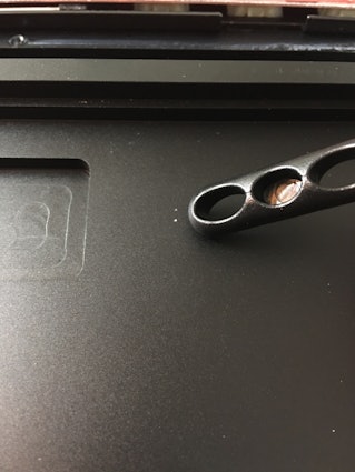
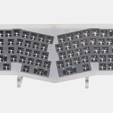
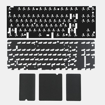
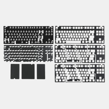
3) See my pictures. In my case, the long soldering tails seemed to be from the CAPSLOCK, SCROLL LOCK, and NUM LOCK LEDs. You can see where they had started to scratch into the powder coat of the chassis. I used a small pair of dikes/snips to trim the tails down (be careful, don't lose those metal bits).
4) Now, we need to insulate/separate the PCB from the chassis. I have to say, it is FREAKING BONKERS that there is no plastic barrier of some sort. I used electrical tape strips (See pic). You want to use something that has a low chance of being worn through (More on that in a minute).
5) Reassemble - Don't forget to reconnect the USB. You should be good now!
This Keyboard is great. Fantastic. But this is a crippling flaw without some sort of fix.
MASSDROP and IKBC - I propose you guys work on sending out your customers *SOMETHING* to drop in between the PCB and chassis. You currently have a small square of plastic over the middle of the board - but more is needed. Future revisions of this board need at least 2-3mm of additional clearance AND an insulating layer, but for us early adopters you should take the initiative and send us out something. There is no reason to make us ship these boards back to you, it would be cheaper (and better service) to send something out.
Assuming there aren't any other points of contact on my board, I should be good - probably for years. BUT if something is very lightly contacting the electrical tape I may find myself doing some maintenance in the future.
I hope this helps everyone, I think the board is worth it - Truly.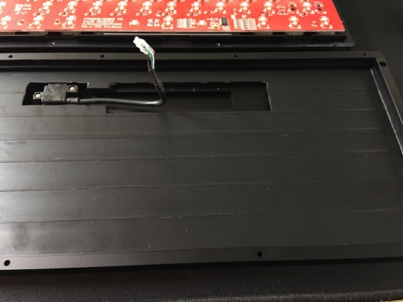
Thanks to the other posts in this discussion, I took it apart and determined I also had some shorting out between long soldering legs and the chassis.
THIS IS EASILY FIXED - NO WARRANTY SEALS NEED TO BE BROKEN - THERE IS NO REASON NOT TO DO THE FOLLOWING IF YOU HAVE ANY LEVEL OF CONFIDENCE!
1) Use the plastic cover that came on top of the board and flip the keyboard over on it - this gives it a little extra stability rather than having the weight of this monster sit right on your keys.
2) Take out all 11 screws. I used a small allen wrench. Get the screws out of their barrels and put them aside (you will be flipping the back over and they will go everywhere if you don't).
3) CAREFULLY lift the bottom of the chassis just a little bit, and get your hand in there to disconnect the USB cord from the harness on the board. BE GENTLE, DAMN YOU!
3) See my pictures. In my case, the long soldering tails seemed to be from the CAPSLOCK, SCROLL LOCK, and NUM LOCK LEDs. You can see where they had started to scratch into the powder coat of the chassis. I used a small pair of dikes/snips to trim the tails down (be careful, don't lose those metal bits).
4) Now, we need to insulate/separate the PCB from the chassis. I have to say, it is FREAKING BONKERS that there is no plastic barrier of some sort. I used electrical tape strips (See pic). You want to use something that has a low chance of being worn through (More on that in a minute).
5) Reassemble - Don't forget to reconnect the USB. You should be good now!
This Keyboard is great. Fantastic. But this is a crippling flaw without some sort of fix.
MASSDROP and IKBC - I propose you guys work on sending out your customers *SOMETHING* to drop in between the PCB and chassis. You currently have a small square of plastic over the middle of the board - but more is needed. Future revisions of this board need at least 2-3mm of additional clearance AND an insulating layer, but for us early adopters you should take the initiative and send us out something. There is no reason to make us ship these boards back to you, it would be cheaper (and better service) to send something out.
Assuming there aren't any other points of contact on my board, I should be good - probably for years. BUT if something is very lightly contacting the electrical tape I may find myself doing some maintenance in the future.
I hope this helps everyone, I think the board is worth it - Truly.
TheZlog
121
Jan 24, 2017
bookmark_border
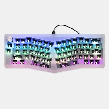
TheZlogOne last question: Has anyone figured out if you can have a backlight that is always on + a reactive effect?
For example: green backlight with yellow reacting keys. Is this possible?
For example: green backlight with yellow reacting keys. Is this possible?

TheZlog
121
Jan 25, 2017
bookmark_border
JawadIt's pretty easy, honestly. You want to be careful when you lift the back off after removing the screws because you need to disconnect a little cable from the board. It was a bit snug on mine, but I just worked it free with my fingernails. Don't pull on the actual wire and you'll be fine. If you have someone to hold the back while you fingernail the plug free it will be even easier, but I did it solo.
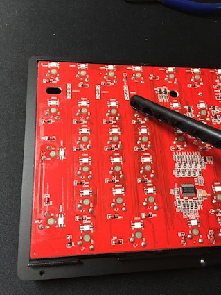
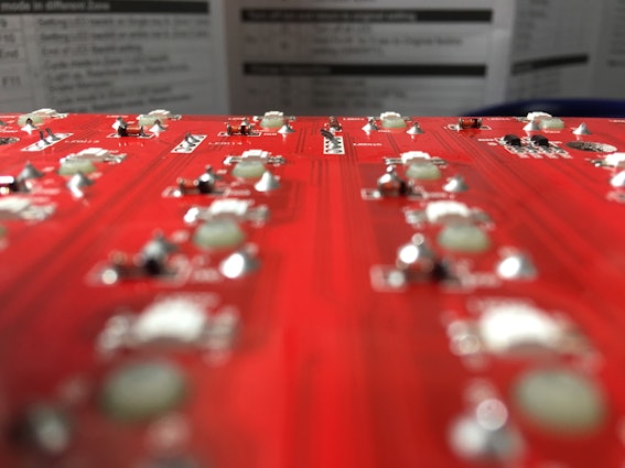
Solder legs are fairly soft. If you have a pair of dikes that would be best, but even fingernail clippers will likely do the job. You don't want to snip it flush with the board, rather you want to snip the leg that extends past the actual solder. If you look at your board, there will be plenty of examples of proper-length legs. Make sure you don't pry or pull when you snip, just pinch them off.
I must say I'm proud of my tape job, lol. If you look at the picture (I added it to this reply again) you can see the tape strips going horizontally. I gave them just a tiny bit over overlap to make sure there weren't any gaps. I used a sharp knife to gently cut around the part that the wire is in. When you reassemble, make sure the wire bend goes in there as opposed to getting smooshed between the PCB and the case!
Also, I went and edited my post with labels for the pics. I hope they line up properly.
Hikasaki
1282
Jan 25, 2017
bookmark_border
TheZlogUnfortunately no, there are no layering to the RGB lighting.


TheZlog
121
Feb 8, 2017
bookmark_border
DaveerI don't think it's possible, which is a bit of a bummer. I touch-type, though, so I just leave it with a customized steady backlight or the raindrop mode if I'm feeling spiffy.
FaceMcBashy
140
Feb 10, 2017
bookmark_border
TheZlogDo you think mine has the same issue?
https://www.massdrop.com/buy/ikbc-87-rgb-mechanical-keyboard/talk/1594746
What kind of screw driver do you use to open it up?
https://www.massdrop.com/buy/ikbc-87-rgb-mechanical-keyboard/talk/1594746
What kind of screw driver do you use to open it up?
Blackwall
0
Jul 14, 2019
bookmark_border
TheZloghi! any chance the casing can house other pcbs/plates of the tkl layout? I'm asking in case something happens to the board or I end up wanting another setup. Does the plate rest on notches etc?
Related Products


Drop Refurbished
Like-new products you can trustDrop Rewards
Get $5 for every 500 points you earn! Learn more
Drop Keyboard Club
Become a member and expand your keycap collectionCollaborate With Us
For Brands & DesignersFollow Drop
If anyone did receive one with QC issues, I would seek getting it replaced. I'm very surprised by the build quality here.
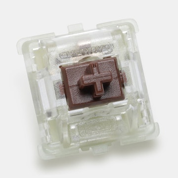
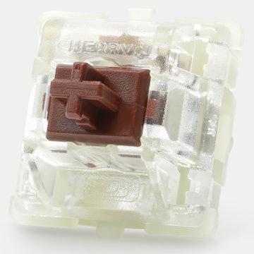
Not sure if they are Cherry brand or not, but the long keys use Cherry-style stabilizers rather than those little metal bars that break.
This means a couple of the keys have a bit of a knock to them, but I'm going to get some O rings to put on space, backspace, enter, and some of those keys that get mashed a bit harder. The rest of the keys sound very crisp due to the weight and solidness of the chassis. I'm in heaven.