Click to view our Accessibility Statement or contact us with accessibility-related questions


Showing 1 of 1309 conversations about:

Inanis
515
SEALWoodworking
May 28, 2015
bookmark_border

Kaan
297
May 28, 2015
bookmark_border
InanisI had the same issue, every time I screwed in the case, random switches stopped working, it was frustrating, as it only happened when the case was screwed in
That's why I checked for the power usage too, I was afraid the keyboard was pulling 500ma or something because of the insulation issues, luckily that wasn't the case, the usage is almost 0ma
I've used paper with my current keyboard as an insulator (I line my keyboards with sound insulator sponges, in this case, that wasn't enough)
Do you also have the Vortex Silver case?
That case also has too many support fins, I destroyed the entire bottom row, it was touching the diodes, at least I thought that was the issue, it might be a more general insulation issue
In retrospect, I would use scotch sellotape to cover the entire inner case and not destroy the support fins unless I really had to (Rev 1.01b requires you do destroy a part of the top row, I'm not 100% sure about the bottom row tho, the bottom row is the same between the 1.02 and 1.01b)
If you're lazy, you can just put a layer of thin packaging plastic under the PCB and put the pcb on that plastic, yet sound-wise speaking, I wouldn't like that
There are many options, I'm going to scotch tape my next case, use sound insulator sponges/tapes, and maybe put in some paper too, the more you fill the keyboard case, the better the sound becomes

Inanis
515
SEALWoodworking
May 28, 2015
bookmark_border
KaanYou are spot on, I am using Vortex silver case. I'm hoping I can put a little bit of liner in there and then the problem will go away. I forgot the little alan wrench that the case screws need, so I can't take it apart until I get back home. I use drawer liner on my other 60% in an aluminum case and it does a good job at handling the sound absorption. I was just lazy and skipped that step on this one. I shouldn't have! Lesson learned.
I was so dissapointed today trying to use my board at work for the first time and finding a whole row didn't work! And then even more frustrated with myself for not having the proper tools on hand to take it apart and investigate it further.
I was so dissapointed today trying to use my board at work for the first time and finding a whole row didn't work! And then even more frustrated with myself for not having the proper tools on hand to take it apart and investigate it further.

Kaan
297
May 28, 2015
bookmark_border
Inanis:)
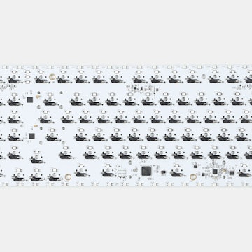
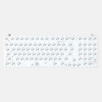
As I was debugging the issue, I checked how the bottom diodes line up compared to the bottom row of the case, it seemed they were touching, so I marked the diode spots with a marker, removed the aluminium with a plier and used my dremel to drill/polish
If you also experienced the same issue with the same case then I guess this step is necessary
Luckily, the aluminium doesn't heat up and it's easy to remove with a dremel, it just produces aluminium dust, one also needs to be careful of the dremel slips (luckily I didn't damage the visible parts of the case)
I would suggest trying various insulation methods before going the destructive route as it's dangerous
One other concern is diode health, so removing the bottom row might be a good idea if it's within your doability limits, otherwise, I was concerned a bump to the keyboard might shake the pcb and break a diode or sth. like that
Parak
89
Input Club
May 28, 2015
bookmark_border
KaanFor 1.03 on this drop I'll most likely relocate the diodes to the centerline of the switches (between them) where the three holes line up on every row. That spot from what I've seen of the ribbed cases so far should be safe. In addition, the soldering quality on the diodes should get improved due to a new board manufacturer, but I'm also looking into any potential handling concerns so that the diodes are not disturbed during the various shipping stages.

rjradical
3
May 28, 2015
bookmark_border
KaanInstead of scotch tape you may want to look into Kapton tape. It is pretty cheap and designed for electrical insulation. http://www.kaptontape.com/

Kaan
297
May 28, 2015
bookmark_border
ParakThat sounds pretty good actually, I already mourn as I have 4 1.02's and 2 1.01b's (second 1.01b is a replacement, it should have been a 1.02, but oh well)
I have some questions on my mind, I'm sure a lot of us would benefit from the answers as well
1) Do you have any suggestions for the 1.02 owners? (I guess a low temp re-flowing and general securing and isolation is a good idea) 2) Are there any other electronical design differences? (like controller wiring, pcb elements/path changes etc.) 3) Are there plans to use a more secure usb connector? (probably from the inadequate soldering, the current ones are not too secure, they are surface mounted, a pinned usb connector could be more secure -- this is my opinion, as no one reported any usb connector issues, I'm guessing it's not a major source for concern)
It seems the only difference between the pcb revisions are diode placement changes, which seems good as it indicates there isn't anything else to change / everything else is generally satisfactory

Inanis
515
SEALWoodworking
May 29, 2015
bookmark_border
KaanI (and you) were correct that it was the bottom row of the diodes hitting the bottom fin in the Vortex case. I put a layer of liner inbetween the case and the PCB, screwed it in and everything started working properly. VERY happy that this resolved it.
For anyone putting this in an aluminum case, make sure you put a layer of something inbetween your case and PCB! It looks like going forward @Parak is accounting for this issue so hopefully it won't be a problem any longer.
For anyone putting this in an aluminum case, make sure you put a layer of something inbetween your case and PCB! It looks like going forward @Parak is accounting for this issue so hopefully it won't be a problem any longer.
Parak
89
Input Club
May 29, 2015
bookmark_border
Kaan1) I generally suspect that after a board is installed and working any components will not need reflowing, especially since mixing unleaded and lead free solder can lead to some unexpected results, and having extra solder on the joint can sometimes be weaker than having a little. The key is seeing a fillet , and not covering a lead completely.
2) Since it's just the bottom row having issues, I'll probably just move up the diodes there and leave the rest as is. The other change to the board is addition of an integrated flashing pinout for large volume flashing - the 4 pin will still be there, but it won't be provided by default, since there were reports of folks having it poking out of the case too much, and those that want to use it for poking at the bootloader can still do that by soldering one on. The PCB will be rewired as the result, but will obviously be prototype tested first before large volume ordering - we do this for all projects.
3) In typical use, the two plastic pegs that go through the pcb on the usb connector are supposed to provide sufficient bracing against constant removal and insertion of cables - it's the upwards lifting force that is iffy, but that goes for any smd component on any pcb. As I understand, the extra tension was there in metal cases with diodes around the usb connector resting on the case rib, causing downward force on the connector when plugged in. That was fixed in 1.02, and I haven't heard of people losing their usb after that.. but I'm still looking into various options just to see what's possible. Doing through hole connectors on a mass produced board is actually a bit trickier than smd, however.


Long story short, nothing is ever easy.