Click to view our Accessibility Statement or contact us with accessibility-related questions


PRODUCTS YOU MAY LIKE

Trending Posts in Mechanical Keyboards

DaveKaretnyk
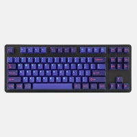
Mode Tempo with Red Samurai
Mode Tempo (60%) with GMK Red Samurai & Mode Lotus keycaps
Apr 25, 2024


dvorcol
Support for Alternative Layouts
This is a summary of how alternative layouts have been supported by kits such as Colevrak and Homing. It is not a discussion of alt layout performance and development, but if that interests you I highly recommend starting with Pascal Getreuer’s A guide to alt keyboard layouts (why, how, which one?). It’s a concise and comprehensive overview with links to some great sites that go deeper. He also has a separate Links about keyboards page. The Keyboard layouts doc he recommends explains layout goals and metrics in detail, summarizing the alt layouts discussed here as well as more than one hundred others. Sculpted-profile The majority of custom keycap sets are sculpted-profile (Cherry, SA, MT3, KAT, etc. - more on profiles generally here) so let’s start there. Because each row has a unique keycap shape, alt layouts require a unique keycap for each legend that moves off its QWERTY row. At first there were two The Dvorak layout was patented in 1936 by August Dvorak & William L....
Apr 23, 2024
CousinTimmy
Promo codes for stack Macropad v2
is there any promo codes right now that work with the STACK OVERFLOW THE KEY V2 MACROPAD? link:https://drop.com/buy/stack-overflow-the-key-v2-macropad?searchId=ead314359856d5486d35f4713cff32e9
Apr 23, 2024

Robbedoes
*Help* Screw in stabilizers not fitting in Dropshift V2 keyboard
I'm trying to build a mechanical keyboard with screw in stabilizers, I've build some mechanical keyboards with click-in stabilizers, never with screw in. Somehow one of the pins of the metal top-part collides with the screw in stabilizer of the numpad "enter key". I already tried grinding of a bit of the pin that collides with the stabilizer, but unfortunately I can't make it fit/close properly. You can see that the pin of the toppart leaves a mark on the bottompart of the stabilizer, see picture 2. What am I missing? Using Durock V2 in a Dropshift fullsize V2. See pictures below, thanks in advance!
Apr 23, 2024

Fukyachickennuggets
Polymer clay
Don't drop crazy cash on custom wood builds! Instead go buy polymer clay and paint. Then you can spend a ridiculous amount of time trying to make it look like you can afford to drop crazy cash on...
Apr 22, 2024
GrEEdYY
HELP PLEASE!
HELP PLEASE! I put noise insulation in the keyboard and after that it stopped working, the only sign of life is 5 blinks of orange light.can do something about it? model:DROP ALTv1
Apr 22, 2024
Drop Refurbished
Like-new products you can trustDrop Rewards
Get $5 for every 500 points you earn! Learn more
Drop Keyboard Club
Become a member and expand your keycap collectionCollaborate With Us
For Brands & DesignersFollow Drop
I found the problem. The PCB plate is held into the frame with 5 screws. There are 3 screws for the top of the keyboard and 2 screws at the bottom.
The 3 screws at the top screw through 3 holes in PCB + PCB plate + Aluminum frame. So PCB is securely mounted to the aluminum frame.
The bottom 2 screws don't go through any holes in the PCB. They are screwed on the bottom side of the PCB plate's edge to the aluminum frame. The screws have small built-in none removable washers. Think of the back of a picture frame, you have little clips that hold the back of a picture frame into the frame itself. The screw's built-in washer can't cover the edge of the PCB plate on the left side of the keyboard. Since the left side PCB plate is not held down to the aluminum frame, you can push down on left side of the keyboard. I tried to adjust the PCB plate to more accurately fit into the aluminum frame, but nothing I did allow the screw to hold the edge of the PCB plate to the aluminum frame on the left side.
I came up with 2 ideas. Put some plastic or wood filler between the bottom aluminum cover and PCB itself. You would not be able to push down because there is no room for the PCB to sink into the bottom aluminum cover. The other idea, which is what I did, is to find the smallest and thinnest washer (Home Depot) and break it into 2 pieces, then use 1/2 the washer, which is big enough, between the screw and PCB plate so that it can hold PCB plate down to the aluminum frame. You can't use the whole washer, because there is no room for the screw and the side of the screw hole on the aluminum frame. Now the left side can't be pushed down.
The design requires the PCB plate to fit into the aluminum frame almost perfectly. Unfortunately a small margin of error can cause the PCB plate to not be held down.
Don't know too much about manufacturing/design, but if they could put the 2 screws on the bottom of the PCB plate through the PCB + PCB plate + Aluminum frame (just like the top 3 screws) then this problem would not exists.