Click to view our Accessibility Statement or contact us with accessibility-related questions


PRODUCTS YOU MAY LIKE

Trending Posts in Mechanical Keyboards


dvorcol
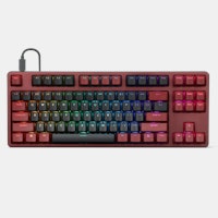
Support for Alternative Layouts
This is a summary of how alternative layouts have been supported by kits such as Colevrak and Homing. It is not a discussion of alt layout performance and development, but if that interests you I highly recommend starting with Pascal Getreuer’s A guide to alt keyboard layouts (why, how, which one?). It’s a concise and comprehensive overview with links to some great sites that go deeper. He also has a separate Links about keyboards page. The Keyboard layouts doc he recommends explains layout goals and metrics in detail, summarizing the alt layouts discussed here as well as more than one hundred others. Sculpted-profile The majority of custom keycap sets are sculpted-profile (Cherry, SA, MT3, KAT, etc. - more on profiles generally here) so let’s start there. Because each row has a unique keycap shape, alt layouts require a unique keycap for each legend that moves off its QWERTY row. At first there were two The Dvorak layout was patented in 1936 by August Dvorak & William L....
Apr 23, 2024
CousinTimmy
Promo codes for stack Macropad v2
is there any promo codes right now that work with the STACK OVERFLOW THE KEY V2 MACROPAD? link:https://drop.com/buy/stack-overflow-the-key-v2-macropad?searchId=ead314359856d5486d35f4713cff32e9
Apr 23, 2024

Robbedoes
*Help* Screw in stabilizers not fitting in Dropshift V2 keyboard
I'm trying to build a mechanical keyboard with screw in stabilizers, I've build some mechanical keyboards with click-in stabilizers, never with screw in. Somehow one of the pins of the metal top-part collides with the screw in stabilizer of the numpad "enter key". I already tried grinding of a bit of the pin that collides with the stabilizer, but unfortunately I can't make it fit/close properly. You can see that the pin of the toppart leaves a mark on the bottompart of the stabilizer, see picture 2. What am I missing? Using Durock V2 in a Dropshift fullsize V2. See pictures below, thanks in advance!
Apr 23, 2024

Fukyachickennuggets
Polymer clay
Don't drop crazy cash on custom wood builds! Instead go buy polymer clay and paint. Then you can spend a ridiculous amount of time trying to make it look like you can afford to drop crazy cash on...
Apr 22, 2024
GrEEdYY
HELP PLEASE!
HELP PLEASE! I put noise insulation in the keyboard and after that it stopped working, the only sign of life is 5 blinks of orange light.can do something about it? model:DROP ALTv1
Apr 22, 2024
Durazell
Want to build a Clicky Mech Keyboard. Where to begin?
Hello all. Am brand new to the idea of building my own keyboard. Have not a clue where to begin this process. I am a Sim Game enthusiast. American Truck Sim, DCS Flight Sim and goes from there. Need some real help on where to start for making my own Full Size, Clickey Mechanical KB. I want each key to have its own backlighting. Are there keys that are better than others for this? Is there a great spot on site for a person who has never even taken a keyboard apart? Let alone fixed or built one? I would like it to fit my theme of Red and Black. Yet maybe have the option of changing things up a bit. Any help at all would be greatly appreciated. Thank you all kindly, Durazell
Apr 20, 2024
Drop Refurbished
Like-new products you can trustDrop Rewards
Get $5 for every 500 points you earn! Learn more
Drop Keyboard Club
Become a member and expand your keycap collectionCollaborate With Us
For Brands & DesignersFollow Drop
PCB: http://dirtypcbs.com/view.php?share=14162&accesskey=f429cad9a82d1292b1013e43a49ba001
Firmware: https://github.com/VinnyCordeiro/tmk_keyboard
The PCB provided on this buy (or at least the one on the previous buy) is based on Microchip's PIC architecture. I have used the ATmega32U2 microcontroller, which uses Atmel's AVR architecture. They are not compatible with each other.
1x ATmega32U2 TQFP32 16x 1N4148 SMT Diodes 4x 0805 SMD resistors -R1&2 - 22 Ohms -R3 - 10k Ohms -R4 - Not connected (I think), see note 1x 16Mhz through-hole crystal 1x button switch 4x Capacitors SMD: -C1 - 10uF -C2 - 1uF -C3&4 - 20uF 2x 20pf 0805 SMD capacitors 1x Mini USB 5 pin female Jack Plug
Note: R4 is connects to pin PD7 on the ATmega Functions of this pin from the datasheet: -HWB/TO/INT7/CTS, Bit 7 HWB, Hardware Boot : The PD7 pin can serve as TO, Timer/Counter0 counter source. INT7, External Interrupt source 7: The PD7 pin can serve as an external interrupt source to the MCU. CTS, USART1 Transmitter Flow Control. This pin can control the transmitter infunction of its state.
Here's a picture of the board: https://i.imgur.com/9ZKQ9Mr.jpg?1