Click to view our Accessibility Statement or contact us with accessibility-related questions


Showing 1 of 36 conversations about:

Jdogz427
4
Feb 10, 2015
bookmark_border
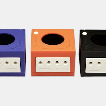
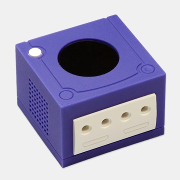
I got mine today in Maryland USA. I have to say i am pleased. I expected the housing to be plastic, but it seems to be metal most likely aluminum, with a what looks like PCB with the key-switch attached so you can solder some leads to it to make something work upon pressing a button. However not being an electrical engineer despite taking several engineering classes, I would have no idea where to start doing something like that.
AlexPk
7197
Community
Feb 10, 2015
bookmark_border
Jdogz427I soldered some LEDs in mine and use it to click with light. Basically just to test the actuation points.

Data
2004
Data
Apr 14, 2015
bookmark_border
AlexPkI want to do this. Can you give a brief explanation of how you did it? I'm mainly curious about the resistors and what you used as a power source.
AlexPk
7197
Community
Apr 14, 2015
bookmark_border
DataYea!
The little Varmilo board actually came with a little SMD resistor so I pretty much just soldered a USB cable to use a 5V power source such as a generic phone charger or your computers USB.
The resistor on the board is 189 ohms and the LEDs are 2V so on a 5V power source you'd have 3V leftover and with 189 ohm resistor it ends up being ~16 mA which works out fine for the LEDs I have. My computers USB has a 500 mA limit so even if I held down all 9 it would only be ~150 mA of draw. Now, I wouldn't hold down all of them because I'm pretty sure power dissipation would become an issue, but I think 4 at a time would be below a 1/4 watt.
To be safe you could put an extra ~150 ohm resistor between the LED and it would bring the current down to ~10 mA, but I think that would be overkill for something like this.
If anyone more knowledgeable wants to correct any of that please do. This is just something I did for fun based on my understanding.
Data
2004
Data
Apr 14, 2015
bookmark_border
AlexPkYes, I see it now. The resistor is so small I never caught it. I have some LEDs with a 20mA peak current so I should be all set. Thanks, Alex. I will post the results!
Data
2004
Data
Apr 15, 2015
bookmark_border
AlexPkYeah it didn't turn out so well. I had a few pins that just wouldn't take solder. Then when I soldered the negative leg to my USB cable the entire pad came off the PCB. I don't see any way to repair it. So that's that. Oh well, it was worth a shot. Still works as a switch tester. :P
AlexPk
7197
Community
Apr 15, 2015
bookmark_border
DataHahah yea I had the same issue with the solder not taking. For some reason the holes on the board aren't metal so it just won't attract solder. Don't remember how I got around it.
For the pad...you could try making a new pad out of solder?
For the pad...you could try making a new pad out of solder?
Data
2004
Data
Apr 15, 2015
bookmark_border
AlexPkYeah, I might tinker with it. I'm also exploring having a new custom PCB made for it. That's how much the solder joints frustrated me. :P
Related Products


Drop Refurbished
Like-new products you can trustDrop Rewards
Get $5 for every 500 points you earn! Learn more
Drop Keyboard Club
Become a member and expand your keycap collectionCollaborate With Us
For Brands & DesignersFollow Drop