Click to view our Accessibility Statement or contact us with accessibility-related questions


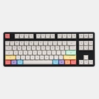
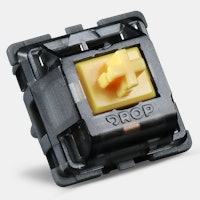
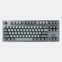
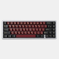
PRODUCTS YOU MAY LIKE


Trending Posts in Mechanical Keyboards
Ike4948
Silent Holy Panda X?
I ordered some Holy Panda X switches, and I fell in love with them. They are a joy to type on. There's just one problem. The place that I use my keyboard to type the most is obviously at work, which is a problem if I want to use the Holy Panda X in the office around a whole bunch of people. I really don't want to torture my coworkers with the clack of these switches. I'd rather they still liked me. The good news is that, for me, the actuation of the Holy Panda X is the best part. I could take or leave the sound it makes; even if it is fantastic. Which leads me to my conundrum: is there another "silent" switch that feels similar to the Holy Panda X? Is there a piece I can remove from the Holy Panda X that would allow me to make them silent? Or am I going to have to wait and see if Drop will drop a Silent Holy Panda X for the in-office mech community?
Apr 28, 2024


DaveKaretnyk
Mode Tempo with Red Samurai
Mode Tempo (60%) with GMK Red Samurai & Mode Lotus keycaps
Apr 25, 2024


dvorcol
Support for Alternative Layouts
This is a summary of how alternative layouts have been supported by kits such as Colevrak and Homing. It is not a discussion of alt layout performance and development, but if that interests you I highly recommend starting with Pascal Getreuer’s A guide to alt keyboard layouts (why, how, which one?). It’s a concise and comprehensive overview with links to some great sites that go deeper. He also has a separate Links about keyboards page. The Keyboard layouts doc he recommends explains layout goals and metrics in detail, summarizing the alt layouts discussed here as well as more than one hundred others. Sculpted-profile The majority of custom keycap sets are sculpted-profile (Cherry, SA, MT3, KAT, etc. - more on profiles generally here) so let’s start there. Because each row has a unique keycap shape, alt layouts require a unique keycap for each legend that moves off its QWERTY row. At first there were two The Dvorak layout was patented in 1936 by August Dvorak & William L....
Apr 23, 2024
CousinTimmy
Promo codes for stack Macropad v2
is there any promo codes right now that work with the STACK OVERFLOW THE KEY V2 MACROPAD? link:https://drop.com/buy/stack-overflow-the-key-v2-macropad?searchId=ead314359856d5486d35f4713cff32e9
Apr 23, 2024
GrEEdYY
HELP PLEASE!
HELP PLEASE! I put noise insulation in the keyboard and after that it stopped working, the only sign of life is 5 blinks of orange light.can do something about it? model:DROP ALTv1
Apr 22, 2024
Drop Refurbished
Like-new products you can trustDrop Rewards
Get $5 for every 500 points you earn! Learn more
Drop Keyboard Club
Become a member and expand your keycap collectionCollaborate With Us
For Brands & DesignersFollow Drop
Re-flow the solder of the diode to try and fix the issue, if it's there (I mean, just touch the solder points of the diode briefly with a solder iron, brief enough to re-liquidify and re-settle the solder)
Like A0.C mentioned, it might be backwards too, so it's a good idea to check the orientation from the small scribblings on
Gateron Clears are the softest switches there is, tooooo soft, you might buy a single Cherry MX Red and use the spring inside to replace it with the Gateron Clear version
You might also push the stabiliser slider further, a lot of people experienced stabiliser issues, this is the fix, the cause is a long story, you might go back in the discussions and find a lot of discussions related to the issue
You also need to put a small amount of paper between the keycap and the stabiliser insert, so it stays in place too, but it's a different issue
In the beginning, it's hard to get costar stabs right, but when you do, the key should be very smooth
On my first mechanical keyboard, a wasd v2, I almost gave up at a similar place to where you are, I'm glad I didn't
kip.ricker, the mechanical keyboards like these have rows and columns that the processor scans, there might be something wrong with one of your columns and it might be preventing all the keys in that column from activating, it might be a good idea to check all the diodes to make sure they are on the right orientation and make sure the solder isn't making any additional connections in general
I had a similar issue with my drop1 infinity keyboard, turned out it was because of an insulation issue, the metal case was touching something, don't know what, it caused the entire column or row to fail, it only happened when I screwed the pcb into the case, so it was extremely hard to detect and fix It's probably not the same issue but, I learned that a problem at a specific place might affect some other keys too
The missing diodes are very disturbing, especially if they ripped the pcb sections with them too, I also suggest everyone to strengthen their usb connectors to the best of their ability, similar to the diodes that fall off, the usb connector isn't very strong either, it's just a small suggestion
(Apart from the issue, this is a nice read in general: http://pcbheaven.com/wikipages/How_Key_Matrices_Works/ - before reading this I didn't know what the diodes were for :)
kip.ricker: That's definitely a row/column issue indeed, is the pcb screwed into a case or is it free? Did you confirm all diodes have the same orientation?
However, I'm guessing you did all these already, after all, it might just be a damaged processor, or a very unfortunate solder blob/splash that's connecting the row/column connection to a ground line, or likely to another row/column
I know massdrop sends replacement pcb's, however with the scale of this issue, I'm guessing those replacements will be delayed, also there is no guarantee that the replacements will be without issues
If it's like the first dropped infinity keyboards, then the small lines on one side of the diode has to point downwards.
An example of how faint those lines can be, here's a picture from their ergodox kit from a while back:
A temporary solution would be to remove the diode of the rightmost 1u diode and put it on the missing key (The key doesn't serve a crucial purpose) In your situation, I would hold the diode with a tweezer and just remove it slowly by heating both ends just a bit, considering they fall off on their own, it should be easy to remove them manually (this is assuming you don't have solder wick, if you have, just wick the solder a bit, then hold the diode with a tweezer and remove it with heat)
Then you can glue it a bit in place and add just a little bit of solder to both sides, to make the key usable
In regards to the diode issue, here was my fix for that (also in another thread here):
Could have had better QC but I am excited these were things I was able to fix.
I toyed around with bending the new diodes wires to fit it into the original diodes solder points, but with this type of diode I couldn't get it to reliably work.
Glad to help.
Thanks for the help everyone!
You appear to not have enough solder on your switches. You need to fill in the whole space with solder not just put a tiny dab on there. If you look at your picture, on the bottom right, there is a switch with almost no solder in the joint. Please check all your joints and make sure that they have enough solder in them as that may be the reason for switches not working. It is also ideal if you use flux with these.
Are you also saying I need to add more solder to the missing diode's lower solder point?
Thanks for the tip.